All Electronic Throttle Controls are fitted with programmable Hall Effect Sensors.
The signals generated by the Electronic Throttle Controls will allow a smooth and precise engine speed control.
The output values are programmable on two channels and hence can be adapted to the customer’s specifications. Electronic throttle controls can be connected directly to the engine management system, or engine Electronic Control Module.
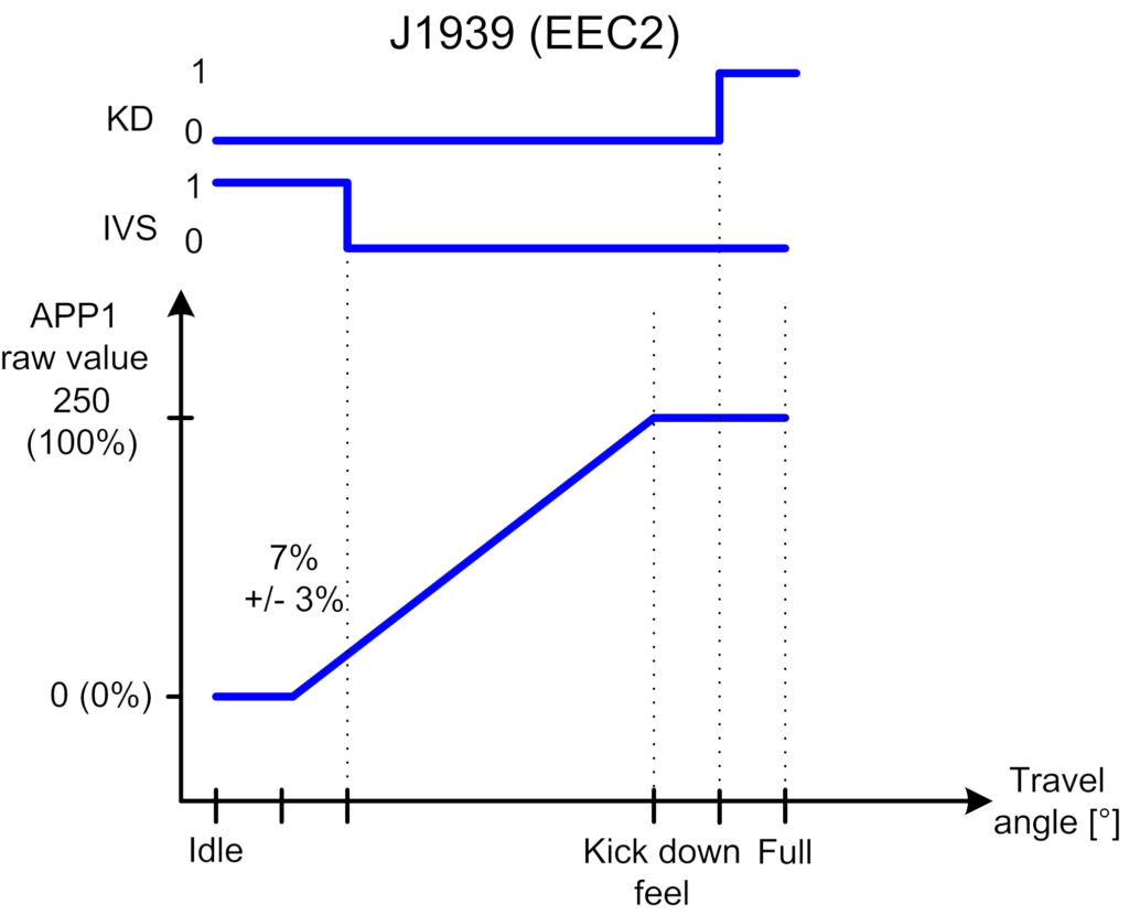
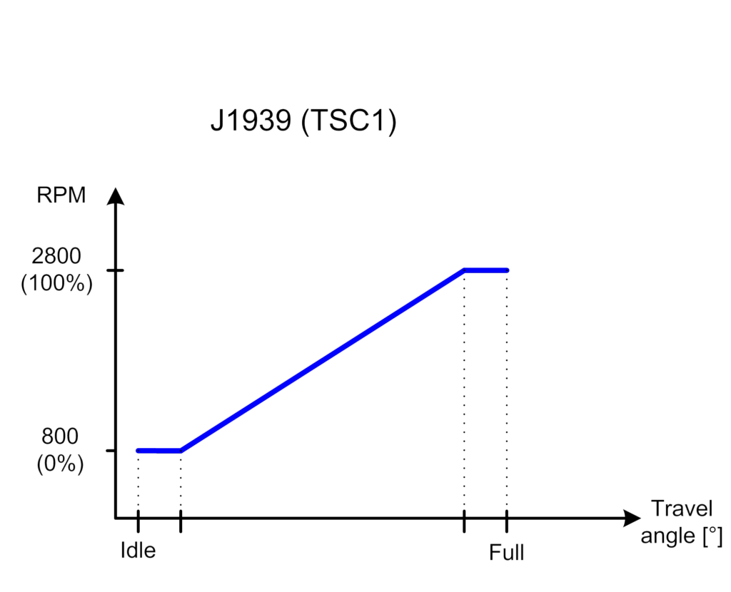
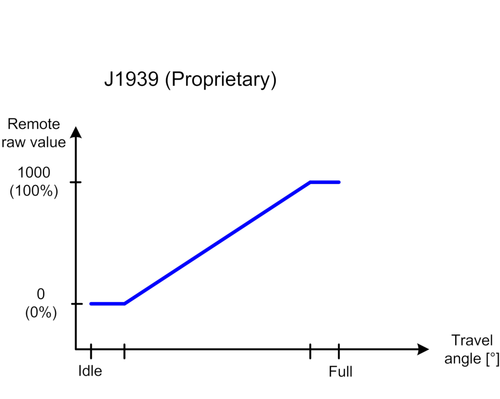
CAN ISO 11898
J1939 Protocol
Factory programmable SPN, PGN, SA and DTC
Factory programmable Baudrate
Customised configurations available
For more information about CAN applications, please contact us.
STANDARD SIGNALS
Two programmable channels per sensor
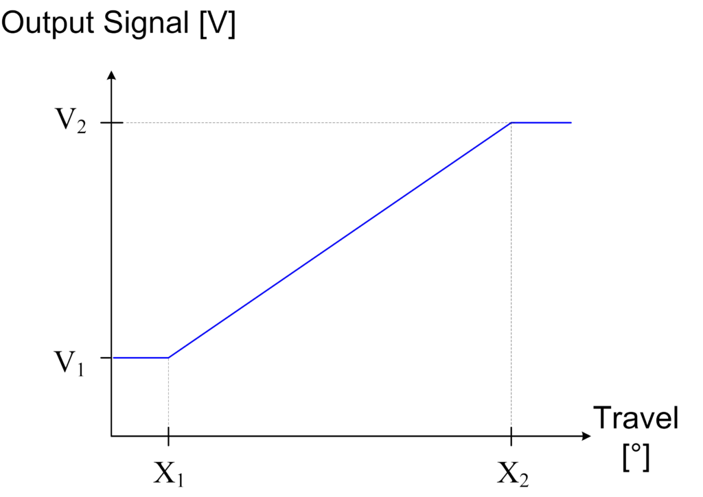
AnalogueSignal(s)
Factory programmable signal slope(s) (V1 and V2)
Increasing (see picture) or decreasing signal(s)
Factory programmable dead bands (X1 and X2)
CurrentSignal(s)
Factory programmable signal slope(s) (I1 and I2)
Increasing or decreasing (see picture) signal(s)
Factory programmable dead bands (X1 and X2)
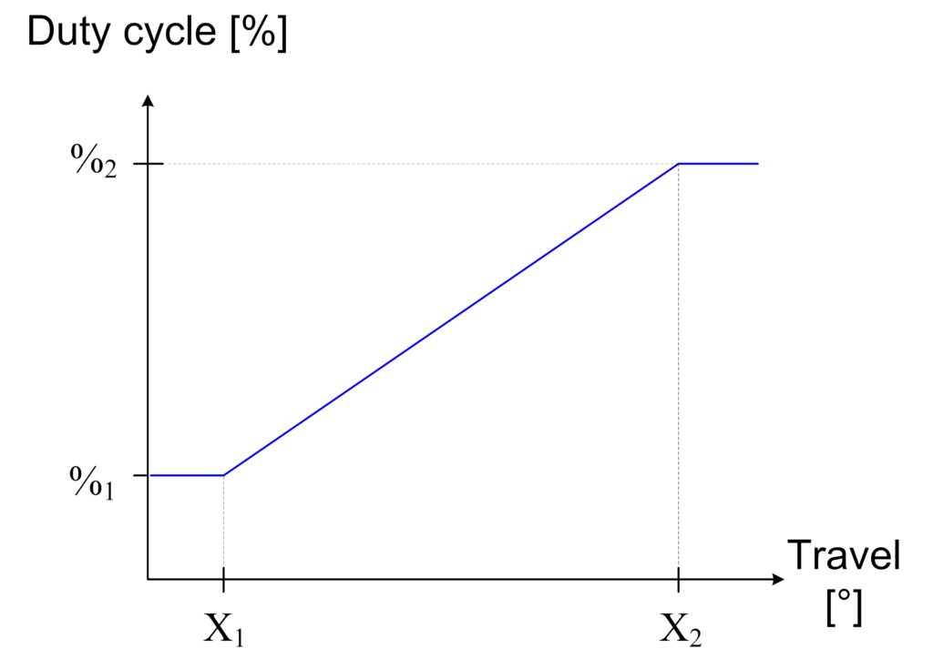
PWMSignal(s)
Factory programmable signal slope(s) (%1 and %2)
Increasing (see picture) or decreasing signal(s)
Factory programmable dead bands (X1 and X2)
Factory programmable frequency
Switch Signal(s)
Factory programmable signal slope(s) (I1 and I2)
Increasing or decreasing (see picture) signal(s)
Factory programmable dead bands (X1 and X2)
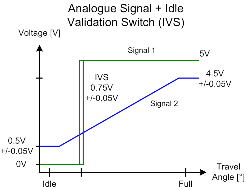
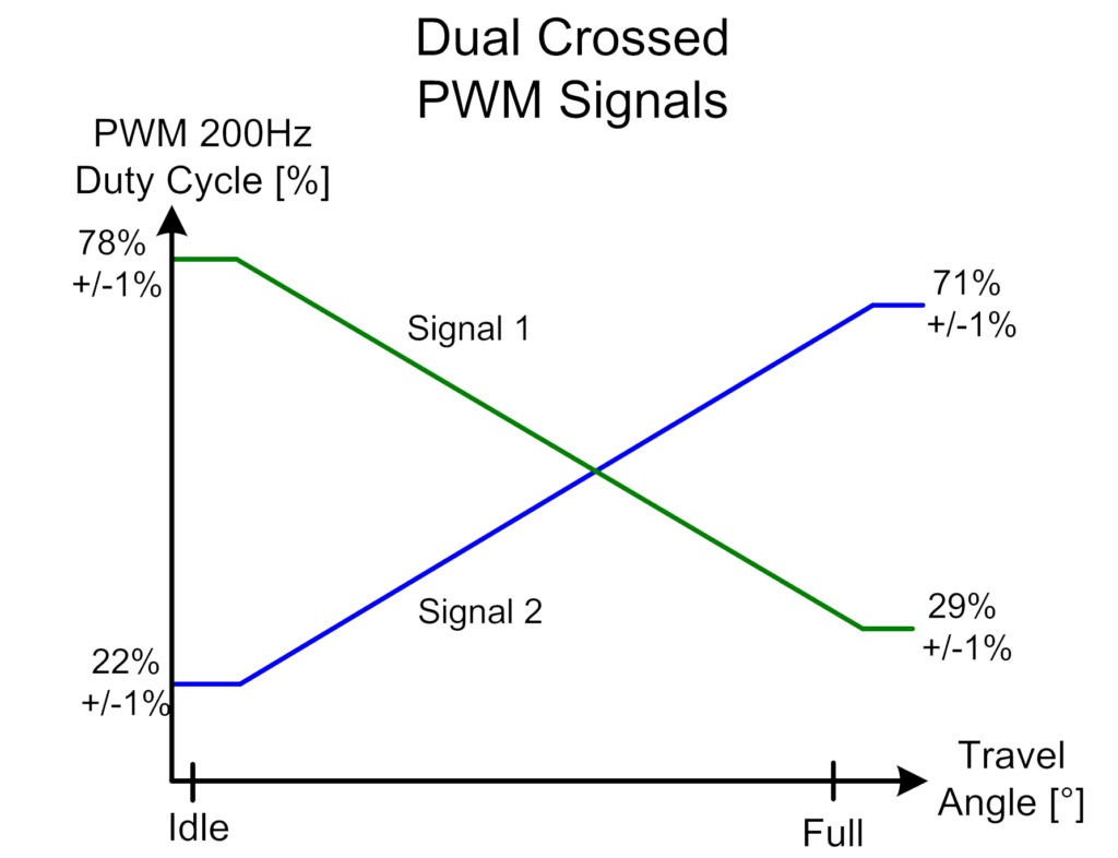
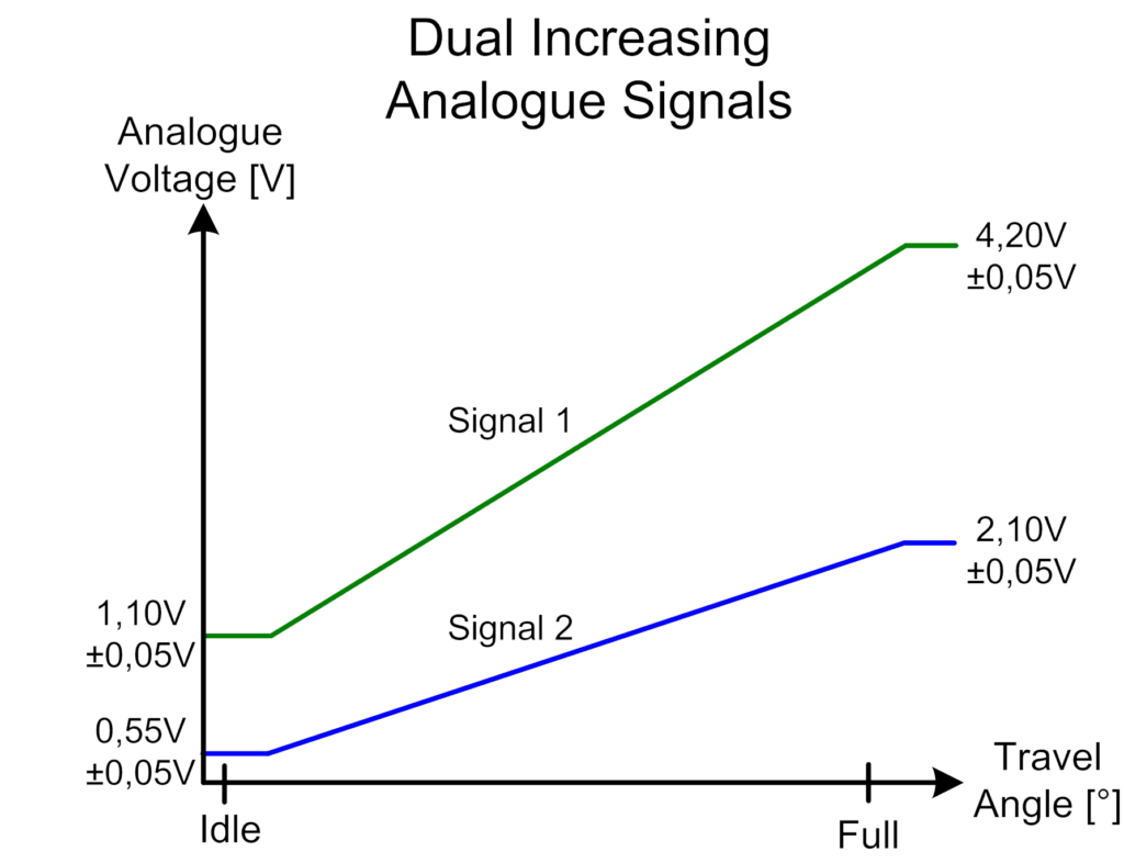
SOME EXAMPLES OF COMMON SIGNAL CONFIGURATIONS
FOR MORE INFORMATION ABOUT AVAILABLE OUTPUT SIGNALS, PLEASE CONTACT US.
Also visit our webpage about our series of products to discover our CAN positions sensors. Check the availability as well as the characteristics and all the options of every device. If you want to order, fulfill our form.
Necessary cookies are absolutely essential for the website to function properly. These cookies ensure basic functionalities and security features of the website, anonymously.
Cookie
Duration
Description
cookielawinfo-checkbox-analytics
11 months
This cookie is set by GDPR Cookie Consent plugin. The cookie is used to store the user consent for the cookies in the category "Analytics".
cookielawinfo-checkbox-functional
11 months
The cookie is set by GDPR cookie consent to record the user consent for the cookies in the category "Functional".
cookielawinfo-checkbox-necessary
11 months
This cookie is set by GDPR Cookie Consent plugin. The cookies is used to store the user consent for the cookies in the category "Necessary".
cookielawinfo-checkbox-others
11 months
This cookie is set by GDPR Cookie Consent plugin. The cookie is used to store the user consent for the cookies in the category "Other.
cookielawinfo-checkbox-performance
11 months
This cookie is set by GDPR Cookie Consent plugin. The cookie is used to store the user consent for the cookies in the category "Performance".
viewed_cookie_policy
11 months
The cookie is set by the GDPR Cookie Consent plugin and is used to store whether or not user has consented to the use of cookies. It does not store any personal data.
Functional cookies help to perform certain functionalities like sharing the content of the website on social media platforms, collect feedbacks, and other third-party features.
Performance cookies are used to understand and analyze the key performance indexes of the website which helps in delivering a better user experience for the visitors.
Analytical cookies are used to understand how visitors interact with the website. These cookies help provide information on metrics the number of visitors, bounce rate, traffic source, etc.
Advertisement cookies are used to provide visitors with relevant ads and marketing campaigns. These cookies track visitors across websites and collect information to provide customized ads.